
At Science Practice we’ve been having a go at DIY microfluidics using just plastic and paper:
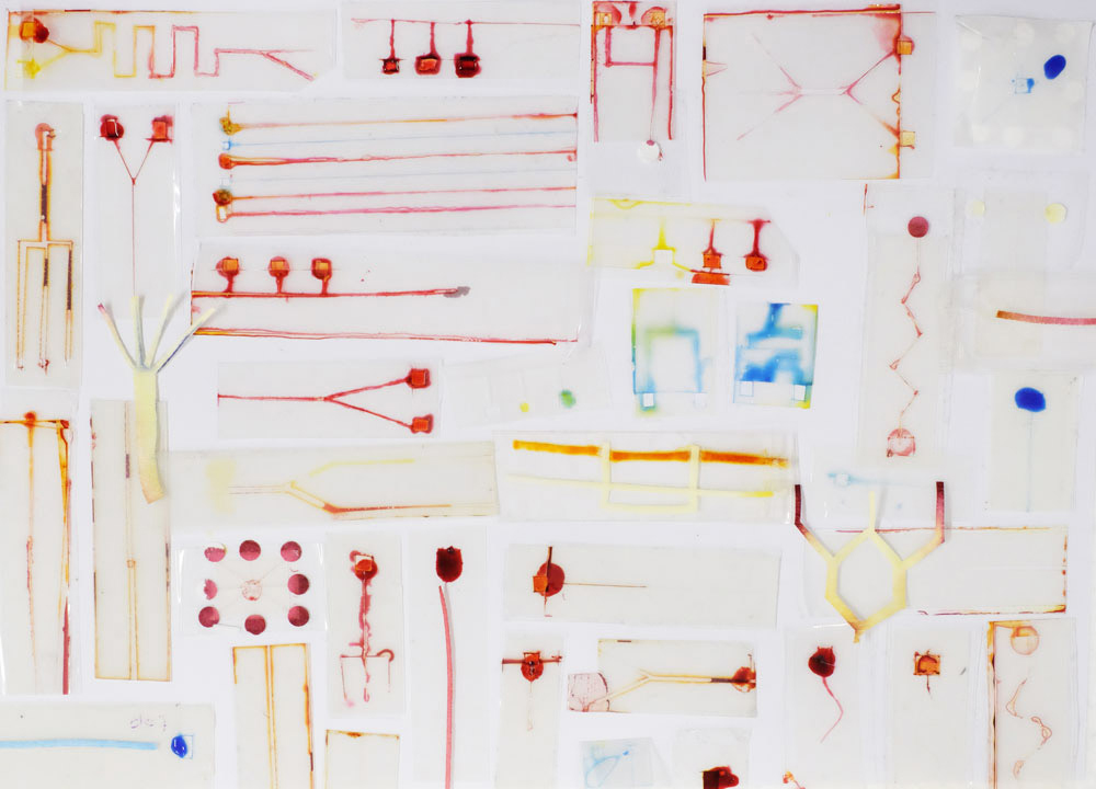
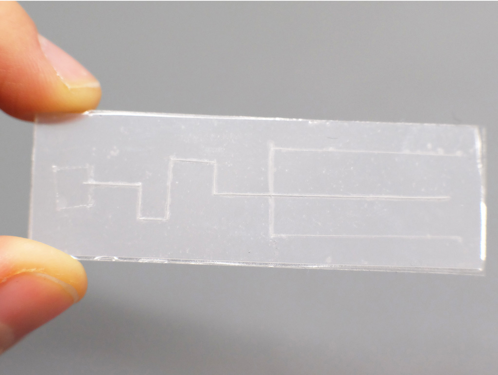
Microfluidic chips made in the Science Practice studio
Attolitre plumbing
The world’s most expensive wine costs about £12/ml, while a run-of-the-mill protein called angiogenin used in biochemical experiments costs about £120/ml. The price of biological reagents is an obvious motivation to shrink experiments to reduce volumes, and in addition, fluids on a small scale behave in interesting and useful ways. Miniaturising experiments to the point where the volumes involved are microliters (down to attolitres) gives them the title microfluidics. Tiny streams of fluid are pumped into micrometer (and smaller) channels which means that an entire experiment/reaction/process involving stages like sampling, mixing and diluting can take place on a lab-on-a-chip smaller than a stamp, automatically and very fast.
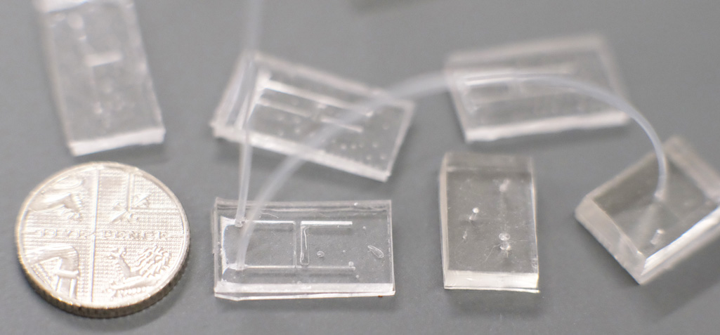
Conventional microfluidics chips made from PDMS, with H and T-junctions connected by microtubing. A five pence coin is shown for scale. Fabricated by friends in the Boutelle lab at Imperial College.
DIY microfluidics
Microfluidics are used as far afield as fuel cells and have found many uses in biological analysis, and specifically in health diagnostics. While they do reduce costs by reducing volumes, the chips themselves are still expensive to produce, requiring a laboratory. Here at Science Practice we are curious about the future of organ-on-a-chip technology, which involves culturing cells in microfluidic chips to mimic organs. Inspired by the push to bring down the cost and technical barriers of microfluidics, we decided to get our hands and our studio dirty and see how close we could get to making our own microfluidics chips in the studio.
Passive microfluidics
A variety of disease markers can be detected in biological fluids and low-tech tests could be used in remote places, in emergency situations and in the home. Paper was popularised as a microfluidics material by the Whitesides group at Harvard University, who patterned paper with hydrophobic areas to create millimetre-sized channels. A feature of microfluidics is the slow and steady laminar flow of fluid which happens in tiny channels. A similar situation occurs when absorbent paper draws in water. This natural wicking by capillary action means that pumps are not needed to transport fluids through paper channels.
Because passive microfluidics don’t require external pumps (and associated equipment like power sources), they can be small, portable, disposable, easy to distribute and operate, low-cost, technically simple to make, and they only need tiny amounts of sample fluid. Passive systems are therefore well-suited for use in the field or in parts of the world without access to advanced manufacturing and clinical technology.
In addition to paper, experimentalists in the lab and beyond have started to replace the PDMS and photolithography of traditional microfluidics with low-tech materials from Shrinky Dinks plastic (in which macro-channels are cut and shrunk down to micro-channels) to Sharpie pens which create a water barrier. We considered a variety of easily available materials for passive microfluidics and decided to start with the following three combinations: Wax-Paper, Paper-Tape, and Plastic-Tape.
Although the pictures which follow may look quite gory, the red fluid is not blood but food colouring diluted 1:1 with tap water (there’s a full list of materials at the end of this post). Since we have no prior experience with microfluidics, and no laboratory or specialist tools, any techniques we have come up with are assured to be low-tech.
Testing microfluidics techniques
Method 1: Wax-paper microfluidics
I was enticed by the child-like simplicity of drawing with a wax crayon on paper, which I came across in a paper by Lu et al. The principle is that wax lines on paper make a hydrophobic barrier to aqueous fluid. For extra absorbent paper which would wick liquid as far as possible I used 55% cellulose paper which is actually an absorbent laboratory wipe.
I melted the wax lines into the paper by microwaving it on a plate for 2 minutes (I also tried a conventional oven). Overall I didn’t find the Wax-Paper technique very useful in the DIY context because it’s difficult to make thin wax lines by hand, and the thinner they are the more likely they are to “leak” and allow fluid to pass through the wax barrier.
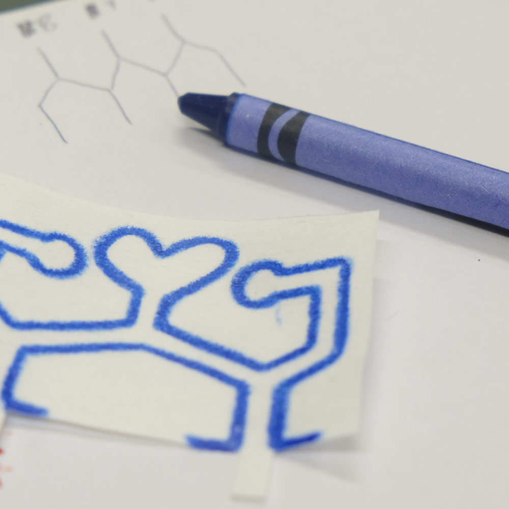
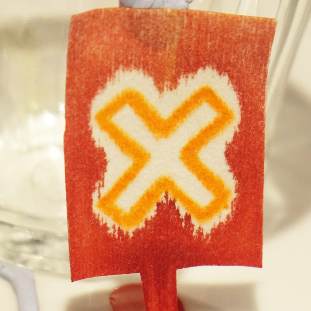
Trying the Wax-paper technique to create microfluidics. Wax lines are best at keeping fluid outside or inside of a closed path, as shown in the bottom row.
Here are some observations which I would keep in mind if developing this method further:
- Even with the sharpest crayons you need to press hard to make thick lines to contain the fluid.
- The wax line expands when heated and there is a transparent water repellent area on either side of the line.
- Wax-Paper microfluidics have a limited fluid capacity. After the channels become saturated fluid starts to overcome the wax barriers and leak out.
- Fluid takes a sneaky path along the thin side of the paper which is hard to cover in wax.
- It’s therefore easier to keep fluid outside of a closed shape or inside a closed shape.
Method 2: Paper-tape microfluidics
The Whitesides group has shown that by stacking layers of paper and tape, a multi-level structure is possible, and with a hole between levels the fluid can “jump” from one level to another, enabling 3D flow. This kind of 3D structure allows for more complicated designs which would not be possible in a single layer.
Since we don’t have the resources to hydrophobically pattern paper in our studio, I used a craft knife to cut paper into the thinnest strips possible to create channels, which ended up being about 1.5 mm wide. To create more interesting microfluidic shapes I layered the paper strips between pieces of tape and was able to get 3D fluid flow. This modification of Whitesides’ method doesn’t require (i) patterning hydrophobic areas onto the paper using photolithography which requires chemicals and UV light or (ii) cellulose paste to fill the gaps between horizontal paper layers where fluid needs to move vertically.
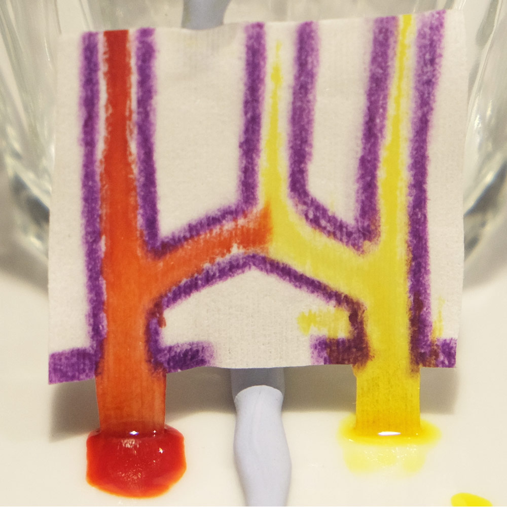
The following are pictures of one of our Paper-tape microfluidics devices with 3D movement of fluid. There are two planes of paper strips separated by a middle layer of double sided tape which has tiny holes in it to let fluid pass from one plane to another. The device is sealed on either side by regular clear tape. In the left image the dashed red circles highlight inter-layer holes which allow 3D motion of fluid:
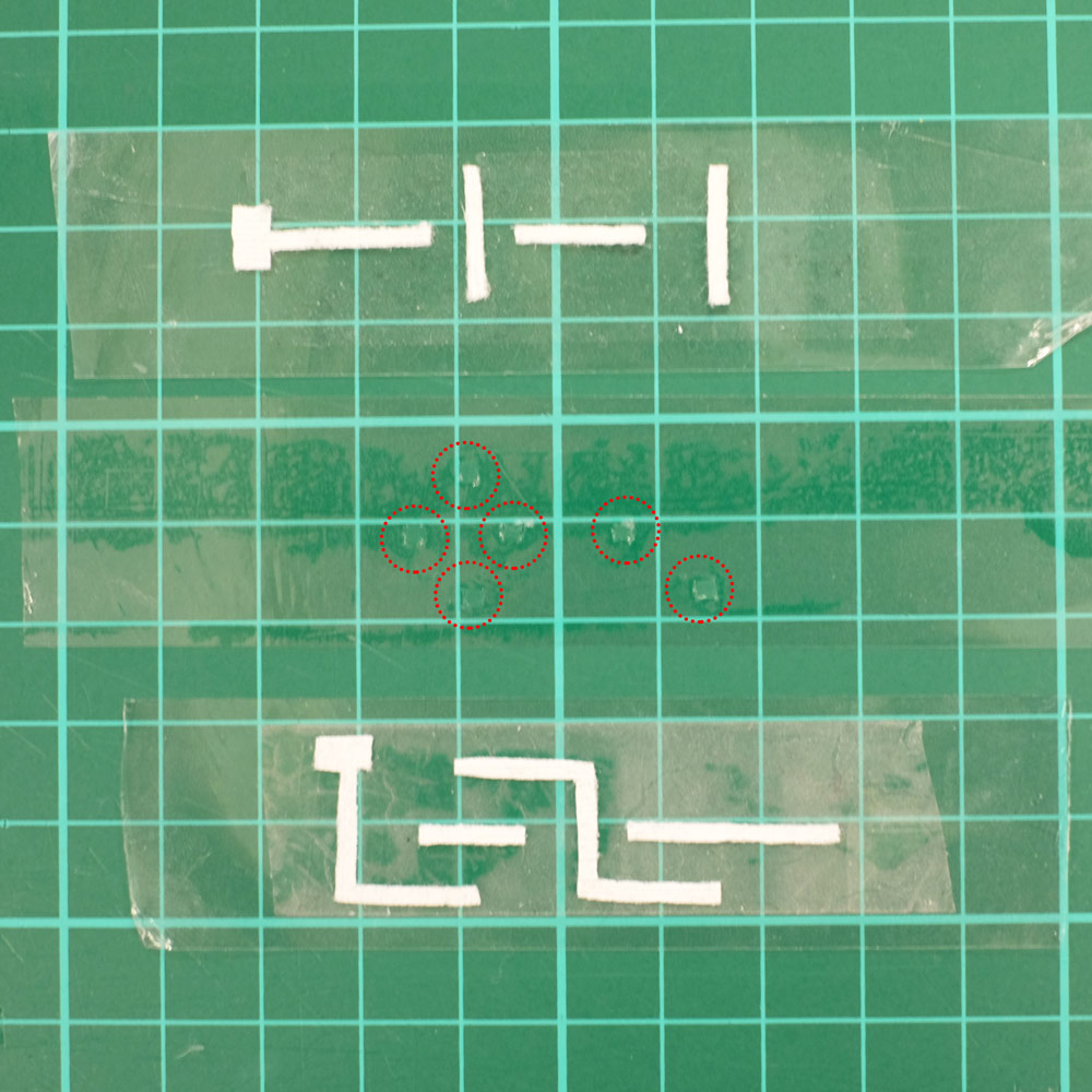
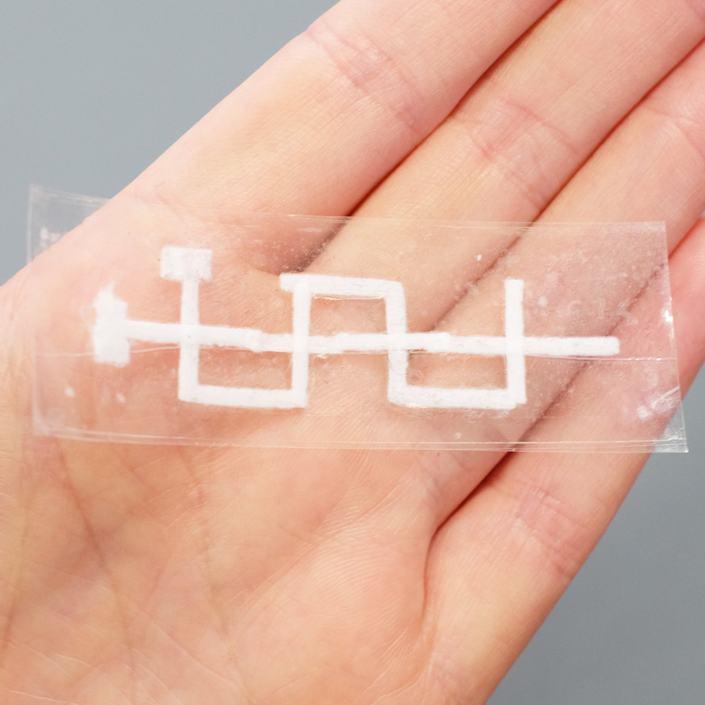
A 3D Paper-tape microfluidics chip. Left: the three layers of the device before assembly, with dashed red circles highlighting holes that allow inter-layer flow. Right: the finished chip.
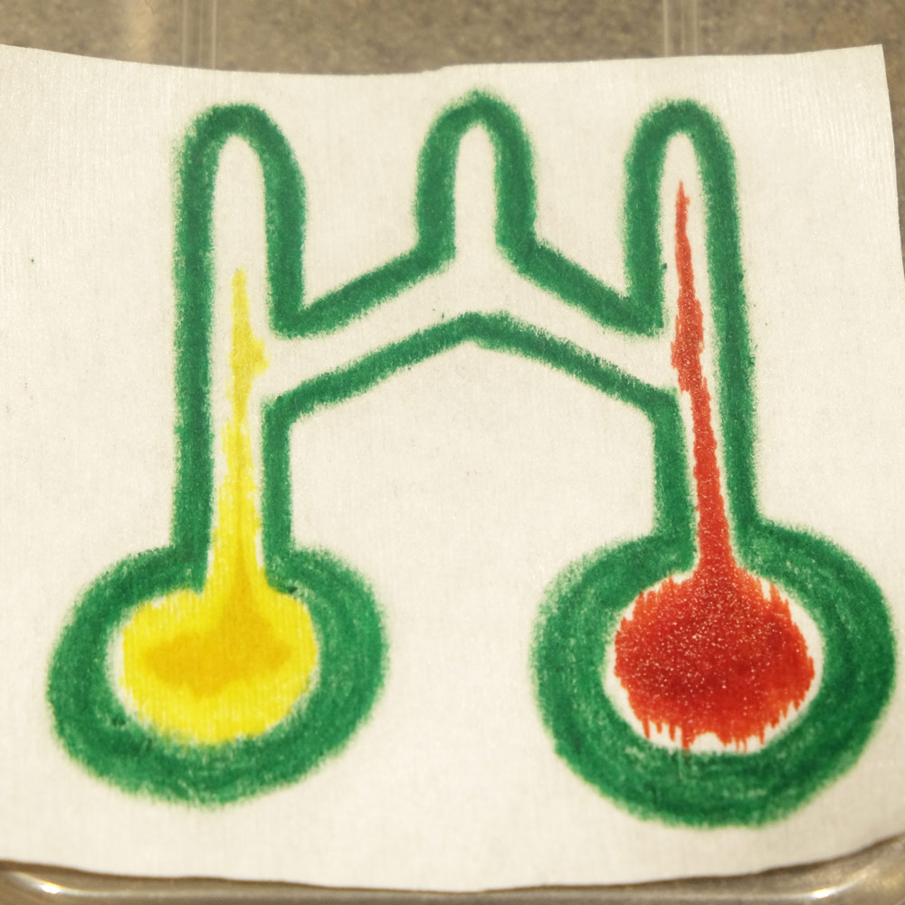
Next is a photo which demonstrates the Paper-tape device’s 3D flow. The thick squares are sample inlets where a drop of fluid is placed. The red fluid weaves under and then over the blue fluid twice. If this chip was 2D then the red and blue would mix, but in this case the streams remain independent:
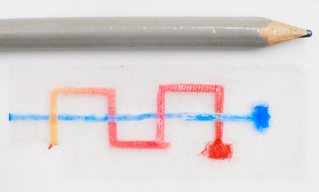
A Paper-tape microfluidic device demonstrating 3D flow. The red fluid weaves under and then over the blue fluid twice, without mixing.
This device has only two layers, but I was able to create a device with fluid moving to four different layers (I didn’t try anything more complex but I think it is entirely possible). I found that vertical flow in both the direction of gravity and against it were possible. The most difficult part of creating these kinds of devices is lining up the strips of paper and the holes.
Pumps not only propel liquid around, but they can also control the speed of flow. With paper microfluidics we can use different papers to create different wicking speeds, for example fluid moves more slowly in coffee filter paper than absorbent laboratory wipes. Another possibility for controlling flow is cutting the paper strips at different angles in the paper. The fastest wicking which is 0.8 mm/s happens when the fluid moves parallel to the grain of the paper, and the slowest which is 0.3 mm/s happens when the fluid moves perpendicular to the grain. Theoretically any speed between these two extremes is possible by cutting at different angles. The following video shows fluid moving through different paper angles as it branches out in a tree-shape cut from a single sheet of paper. The central branch is cut parallel to the paper and is therefore the fastest.
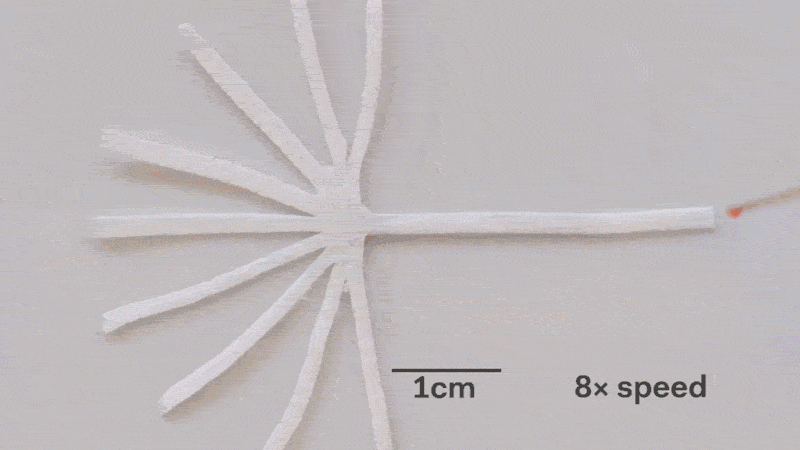
The speed of fluid flow in paper microfluidic channels can be controlled by cutting paper at different angles to the paper grain. Here the central branch has the fastest flow as it is cut parallel to the grain. This animation is sped up 8 times.
Here is a close-up of the paper tree showing that the fluid moving parallel to the paper grain (central branch) is the fastest. In the same time the fluid in the branch with perpenduclar grain has moved only about half as far:
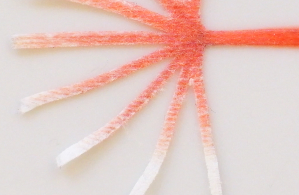
The speed of fluid flow in paper microfluidic channels can be controlled by cutting paper at different angles to the paper grain. Fluid in the the central branch cut parallel to the grain has reached the end, while in the vertical branches cut perpendicular to the grain it has not yet.
Method 3: Plastic-tape microfluidics
This method involves stacking layers of double-sided plastic tape and plastic strips cut from transparency/overhead-projector sheets (sometimes called Mylar sheets). I started by cutting channels about 1.5 mm wide in double sided tape, and sandwiched the tape between two layers of plastic. This creates a channel in the middle layer. The following image shows fluid being drawn up into the channel and then forking into 3 branches:
Microfluidic chips made in the Science Practice studio using the Plastic-tape method with thick channels.
A simplification of this method arose when I observed that I didn’t need to cut a 1.5 mm channel because fluid is drawn by capillary action along any edge. I realised that I could make a channel by merely make a single cut in some plastic sheet and sealing this cut with tape on both sides. Lighter scratches in the plastic also work although it’s hard to maintain a consistent depth when scoring by hand, so it’s easiest to cut all the way through. The following video shows fluid flow in one of these extra thin channels in real time. At its fastest it has a speed of about 1.4 mm/s:
A Plastic-tape chip with thin channels, demonstrating the speed of fluid flow.
The channel needs to be open at the end for capillary action to move fluid along. If it’s not then capillary action needs to work against a pressure build-up in the channel. This means that fluid flow is in one direction only: towards the opening. When designing chips you therefore have to keep in mind that fluids must have an unhindered path to the channel opening. When several streams converge all but one will stop flowing, and this makes mixing streams tricky but not impossible (more on that in another post.)
This open-end requirement can also be used to make a valve that starts and stops flow. Flow can be turned “on” when the channel is open at the end and turned “off” when the end is closed. I thought it would be useful to be able to load multiple inlet pads and only trigger the start of flow on command. I created chips with blind-ended channels which can be loaded with droplets, and fluid only flows when the ends are cut off to open them up:
A Plastic-tape chip with thin channels and branches, sealed off at the end.
The following video shows that fluid only enters the channel when the end of the chip is cut off with scissors. After this point the video is sped up 70 times to show the path of the fluid (which is slower than the previous video because of its tortuous path):
A Plastic-tape chip with thin channels. Fluid is loaded onto the chip, and cutting off the end of the chip triggers fluid flow driven by capillary action. After this point the video is sped up 70 times to show its path.
It is possible to get 3D flow across both the thick the thinly scored channels, but I’ll also save that for a future post.
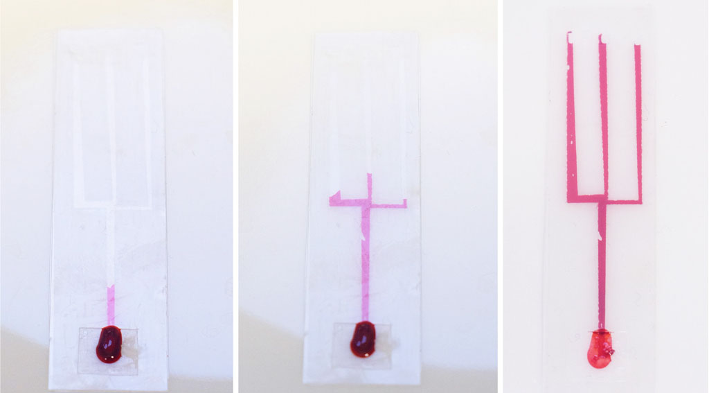
A useful function that these types of microfluidics can perform is distributing a sample to multiple points so that different analytes can be quickly tested at each point. For example a drop of blood could be tested for glucose, proteins and pH. Blood could be dropped into the middle of a device like this, and the blood would quickly be distributed to multiple pads for testing.
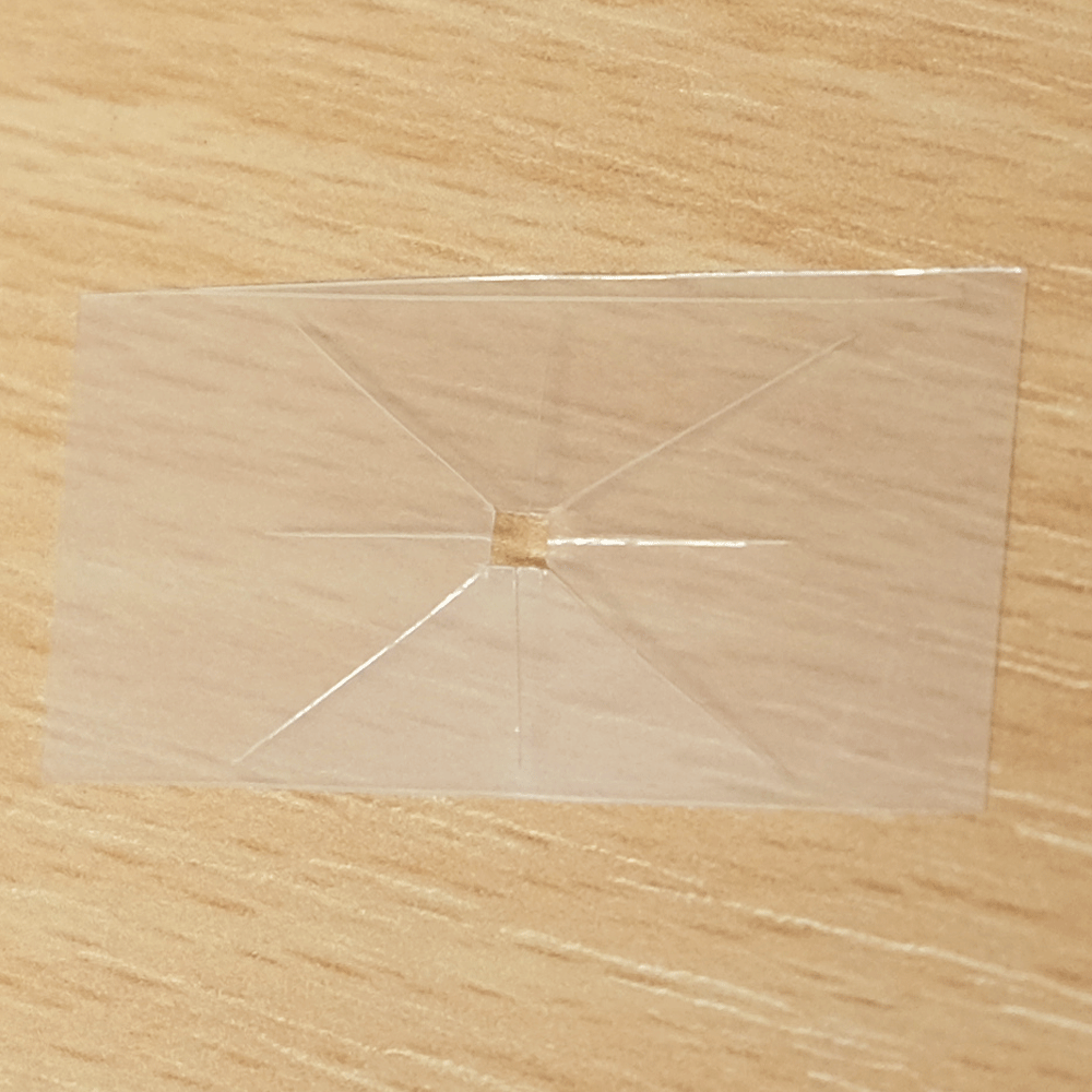
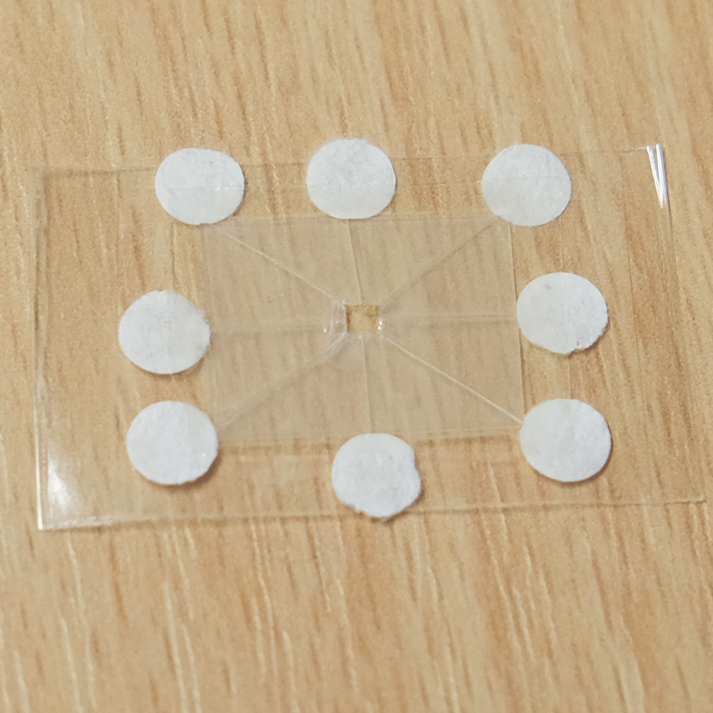
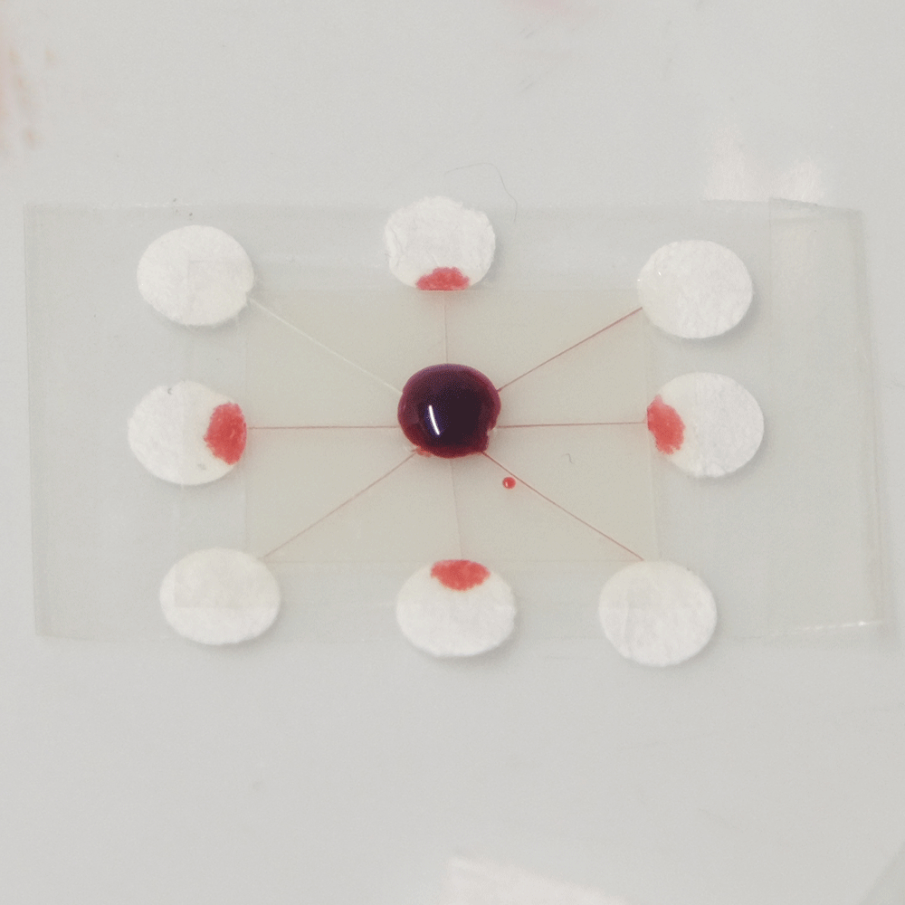
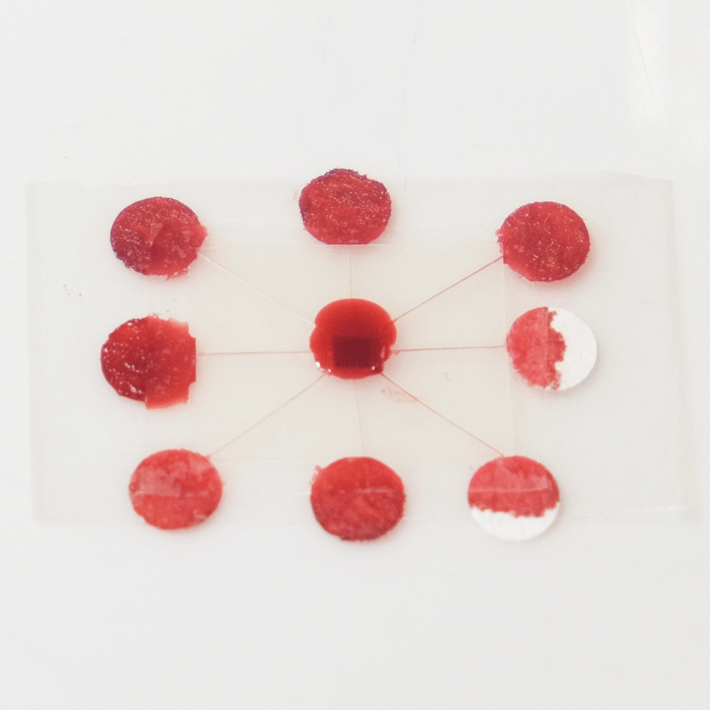
A sample distributing chip. The top row shows construction and the bottom row shows operation of the device. A sample of biological fluid could be placed in the centre of the Plastic-tape chip. It is distributed to multiple points where it could undergo different chemical tests quickly.
I created this sample distributor by scoring channels in transparency plastic and sandwiching this in clear tape on either side. (Maker note: score the plastic almost to the end of the chip, attach sticky tape and then snip off the edges so that it doesn’t fall into eight pieces.) At the end of each channel is a paper pad to draw the sample out of the chip so that a user can add reagents, or have pads that are pre-loaded with reagents. Perhaps a colour change could be observed, or the pads could be removed for further analysis. The paper pads were made by using a punch on coffee filter paper, as super-absorbent cellulose paper was too fibrous to punch.
Verdict
The Wax-paper method was a fun way to get started and get used to working with the paper and fluids, however when made by hand the channels end up being very large.
The Paper-tape method is excellent for fluid travelling over short distances. It has the advantage of allowing multiple channels to converge into one and so mixing is possible. This opens up the possibility of making many useful devices like H-filters and T-sensors as demonstrated in Paul Yager’s work at Washington University.
Of the three methods, I think Plastic-tape with very thinly scored channels has the most potential. The channels are very quick and easy to cut and they use a really tiny sample volume because the channels are so narrow.
However I think it would be great to combine paper and plastic channels in a layered 3D device to get the most of both methods: intricate plastic channels with the mixing capability of paper, and thicker plastic channels for varying speed. Watch this space!
Shopping list
Here’s a list of the materials I used in these experiments:
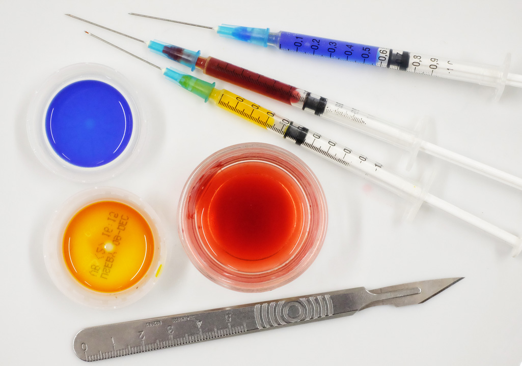
We used food colour as a visible fluid.
- Essential Waitrose natural food colour (red was my favourite because it was the most mobile across all materials)
- Mylar stencil/transparency sheets, 125 micron thick
- 3M Scotch Permanent Double-Sided Tape
- Absorbent laboratory wipes: W50 Polyester Cellulose Wipes by Integrity Cleanroom